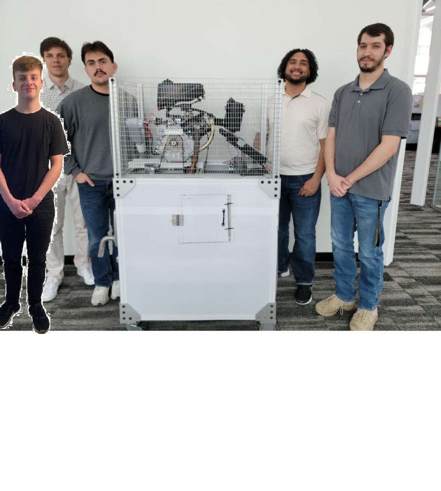
Team 32 Engine Dyno

This project is sponsored by:

The engine-dyno project is our senior design project given to us by the university. Our client, Megan Prygoski, plans to use the engine-dyno in a few mechanical engineering technology courses to demonstrate heat transfer and efficiency. In the future, the engine-dyno may be modified to be used in other courses, but our current focus is to make the engine-dyno a functional piece of equipment that enhances students’ ability to learn about heat transfer and efficiency.  

 Our client requested we check that the inherited engine dyno has a sturdy portable cart, ran without a load, and had a functional thermoelectric loading system. The next items our client requested are necessary to help students learn about heat transfer and efficiency. She asked that the thermoelectric load heat a tub of water. The water temperature is to be monitored with at least 4 temperature probes, and the temperatures will be displayed on an LCD screen. The next request is to circulate the water so that all the temperature probes are within 10% of each other. Also depending on the circulation method, a flow sensor is to be added. The final objective of the engine-dyno was to make the system safe to use. 

Since this is an ongoing project, and our team continued where the last team stopped. Our team had to go through and decide what parts of the project were functional because covid caused the previous group to stop dead in their track. We determined our starting point was to fix the belt that slipped and bounced when we ran it. The belt slippage was caused by the inadequate tension that was applied to the belt. The solution was to add an additional pulley tensioner to tighten the belt. When running the engine, the belt is very stable at the resonant frequencies as the throttle goes from low to maximum. We also determined the cart and loading system passed on to us were functional and worked. 

We used four separate temperature sensors to measure the rise in water. We decided to use a 4x20 LCD Hitachi display because they are easy to use, cheap, and compatible with Arduino Mega. After the temperature probes were working correctly, the flow meter was added to the same board. We decided to use an Arduino mega and not design a complete PCB for several reasons. First, there is a long-term plan to have future groups add several types of sensors to expand the functionality of the engine dyno, so any board designed now would be irrelevant a year from now. Next, we did not know the state of the project since it was inherited, and we did not want to over commit. Finally, Arduinos are widely used and there are many sources online to help future groups easily pick up where we left off.  


For the water tank, the client indicated that a constant temperature throughout would be ideal. Copper pipe was used to make a water flow system. This consisted of copper pipe, a water pump that was rated for 500 L/H, a faucet so that the water can be drained, and a fluid flow sensor to help measure the water going out of the copper pipe. This system was attached to the side of the water tank half an inch above the bottom of the tub. There was an addition of a shut off value which is located before the fluid flow sensor which would allow the water to not be forced back into the water tank when the faucet was set to open. 


The cart needed to have ease of use for users. This meant that a panel had to be made to allow the controls for the cart to be accessible to operators. This panel has a universal ignition switch, choke, Arduino toggle switch for turning on the LCD display, a light switch for turning on the water pump, and an emergency stop. To make sure that the system is safe, the emergency stop shuts off the engine and the water pump. As for user safety, the top half of the cart is covered by fencing which prevents users from being too close to moving parts and from the high amperage / temperature. The bottom half of the cart is shielded by 1/16th inch thick polycarbonate. Two doors were designed for the side panels from the polycarbonate to allow maintenance of the cart but can be closed when in use by 3d printed clips. To keep the doors from closing during maintenance magnets were added to the hinges, which locks the doors in an open position. 

Project Details

Problem Statement

Further development on Purdue’s Portable Engine Dynamometer. Implement and test an electronic control system to dynamically adjust loading and implement a dynamometer control and data acquisition system to perform automated test runs while recording data.

Project Presentation Video

Project Demonstration Video

This project is sponsored by:

The engine-dyno project is our senior design project given to us by the university. Our client, Megan Prygoski, plans to use the engine-dyno in a few mechanical engineering technology courses to demonstrate heat transfer and efficiency. In the future, the engine-dyno may be modified to be used in other courses, but our current focus is to make the engine-dyno a functional piece of equipment that enhances students’ ability to learn about heat transfer and efficiency.  

 Our client requested we check that the inherited engine dyno has a sturdy portable cart, ran without a load, and had a functional thermoelectric loading system. The next items our client requested are necessary to help students learn about heat transfer and efficiency. She asked that the thermoelectric load heat a tub of water. The water temperature is to be monitored with at least 4 temperature probes, and the temperatures will be displayed on an LCD screen. The next request is to circulate the water so that all the temperature probes are within 10% of each other. Also depending on the circulation method, a flow sensor is to be added. The final objective of the engine-dyno was to make the system safe to use. 

Since this is an ongoing project, and our team continued where the last team stopped. Our team had to go through and decide what parts of the project were functional because covid caused the previous group to stop dead in their track. We determined our starting point was to fix the belt that slipped and bounced when we ran it. The belt slippage was caused by the inadequate tension that was applied to the belt. The solution was to add an additional pulley tensioner to tighten the belt. When running the engine, the belt is very stable at the resonant frequencies as the throttle goes from low to maximum. We also determined the cart and loading system passed on to us were functional and worked. 

We used four separate temperature sensors to measure the rise in water. We decided to use a 4x20 LCD Hitachi display because they are easy to use, cheap, and compatible with Arduino Mega. After the temperature probes were working correctly, the flow meter was added to the same board. We decided to use an Arduino mega and not design a complete PCB for several reasons. First, there is a long-term plan to have future groups add several types of sensors to expand the functionality of the engine dyno, so any board designed now would be irrelevant a year from now. Next, we did not know the state of the project since it was inherited, and we did not want to over commit. Finally, Arduinos are widely used and there are many sources online to help future groups easily pick up where we left off.  


For the water tank, the client indicated that a constant temperature throughout would be ideal. Copper pipe was used to make a water flow system. This consisted of copper pipe, a water pump that was rated for 500 L/H, a faucet so that the water can be drained, and a fluid flow sensor to help measure the water going out of the copper pipe. This system was attached to the side of the water tank half an inch above the bottom of the tub. There was an addition of a shut off value which is located before the fluid flow sensor which would allow the water to not be forced back into the water tank when the faucet was set to open. 


The cart needed to have ease of use for users. This meant that a panel had to be made to allow the controls for the cart to be accessible to operators. This panel has a universal ignition switch, choke, Arduino toggle switch for turning on the LCD display, a light switch for turning on the water pump, and an emergency stop. To make sure that the system is safe, the emergency stop shuts off the engine and the water pump. As for user safety, the top half of the cart is covered by fencing which prevents users from being too close to moving parts and from the high amperage / temperature. The bottom half of the cart is shielded by 1/16th inch thick polycarbonate. Two doors were designed for the side panels from the polycarbonate to allow maintenance of the cart but can be closed when in use by 3d printed clips. To keep the doors from closing during maintenance magnets were added to the hinges, which locks the doors in an open position. 

Semester of Project: 

Spring 2022

Team Photo: 

Team Poster: 

Problem Statement/Summary: 

Further development on Purdue’s Portable Engine Dynamometer. Implement and test an electronic control system to dynamically adjust loading and implement a dynamometer control and data acquisition system to perform automated test runs while recording data.

Project Department: 

SOET

Project Presentation Video Embed Code: 

Project Sponsor Website: 

https://polytechnic.purdue.edu/locations/south-bend

Project Sponsor: 

polytechnic-logo

Project Demo Video Embed Code: 

Team Contact: 

abarson@purdue.edu